 Get a Quote
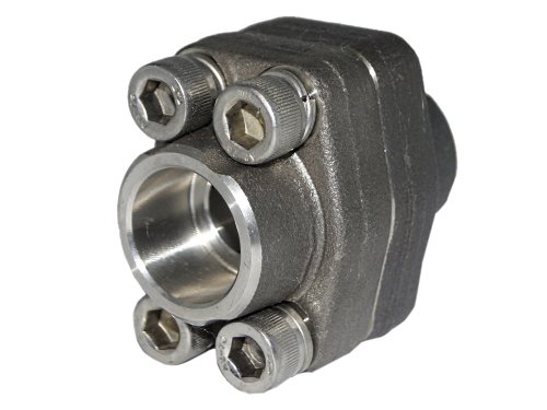
Flanges
Socket Weld SAE Flange
SAE Flange to SAE J518 / ISO 6162 for high-pressure hydraulic connections. Code 61 rates to 3000 psi and Code 62 to 6000 psi; supplied O-ring side, flat (weld) side, or as complete sets.
- Code 61 & Code 62 options
- O-ring / flat / complete sets
- Steel and stainless
Specifications
| Size Range | 1/4" to 5" |
|---|---|
| Design Standard | SAE J518 ISO 6162 |
| Connections | Socket Weld Butt Weld NPT BSPP |
| Material | Steel ST52.3 AISI SS316L |
| Working Pressure | Up to 210 BAR 420 BAR |
| Origin | Italy |
Specifications are indicative and vary by size and manufacturer. Request the full datasheet for exact dimensions, materials and certification.
Typical applications
- Pump and motor port connections
- Manifold and cylinder ports
- High-pressure hydraulic pipework on marine and offshore plant
Ordering & procurement
Ex-stock in Singapore, dispatched within 3 working days. Material / mill certificates (EN 10204 3.1) and export documentation available. Special sizes and materials sourced on request.
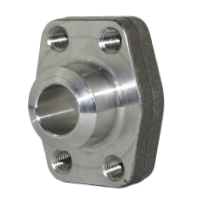
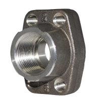
Request a quoteDifferent Connections of SAE Flanges
Product Information of Socket Weld SAE Flanges
1. Specifications:
Socket weld SAE flange is a SAE flange that is made according to SAE J518 / ISO 6162 standards. SAE flanges are supplied for oil hydraulic systems in sectors such as oil & gas, mobile hydraulics, and industrial hydraulics. The acronym ‘SAE' stands for the Society of Automotive Engineers, a group founded in 1905 to set standards for numerous sectors in the engineering area. The flange includes 4 bolt connection holes and is widely used around the world. There are several bolt grades that are matched to install in equipment:
- Bolt grade 8.8: Yellow zinc as standard material with carbon steel flange.
- Bolt grade 10.9: FIZn 240h L is effective for high temperature applications and it is available on request.
- Bolt grade SS304: Standard material with a stainless steel flange.
- Bolt grade SS316: Provides greater corrosion resistance, available upon request.
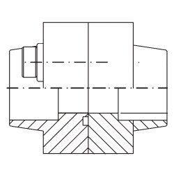
Socket Weld SS316 SAE Flanges 6000#
2. Material:
SAE Flanges are available in two types of materials, which is steel ST52.3 or stainless steel AISI SS316L. The SAE flange body is made from normalized forgings so that it can be used for high pressure applications. There are two kinds of surface for SAE flange which are rough surface and smooth surface. The rough surface is on the pipe end connection side, while the smooth surface is at flange to flange side.
3. Size Range:
For Code 61 series, SAE flanges are available in nominal size ranging from 3/8"NB (DN10) to 5"NB (DN125). While for Code 62 series, SAE flanges size are available from 3/8"NB (DN10) to 3"NB (DN80).
4. Pressure Rating:
There are two series of SAE flanges which define the pressure rating that it can withstand, respectively Code 61 Series and Code 62 Series. The working pressure for Code 61 series ranges from 34 Bar to 345 Bar, depending on the sizes. Whichever bigger the sizes, it will lower the working pressure that SAE flange can withstand. For Code 62 series, the maximum working pressure is 414 Bar.
However, the pressure rating of SAE flanges and connected equipment combinations might vary from each other. For example: if a pipe connected to the flange has a lower maximum working pressure, it will result in an overall lower working pressure of the system. Therefore in a system, the item with the lowest pressure will be the maximum working pressure of the system.
5. Connections Type & Configurations:
For the connections of SAE flanges, it is available in socket weld connection where the pipe is inserted into the recessed area of SAE flange.
SAE flanges are available in two types: O-ring Side and Flat Side. O-ring side SAE flange contains a groove seat to place a rubber O-ring on the smooth surface. Flanges with O-ring have an advantage of preventing leakage as all metal-to-metal flanges are more prone to leakage. While Flat sides of SAE flange are SAE flanges that come with bolt thread either in metric bolt thread or unc bolt thread.
The configurations of SAE flanges are available in O-ring side, flat side or complete set. A complete set of SAE flange is a combination of O-ring side with flat side where it forms a seal between the flat surface and O-ring held in a recessed circular groove in the other half. By tightening the allan cap screws in diagonal sequence, it draws flat side and O-ring side together and compresses the O-ring.
SAE flange complete set is tightened by using socket head cap screws and spring washers according to the recommended torque value. According to SAE J518 standard, the lengths of cap screws are usually shorter than the overall length of SAE flange complete set.
6. Differences between Code 61 and 62 flanges:
SAE Flanges are built in two different code designs which are code 61 and code 62. The following is a summary table: Description
| Description | Code 61 | Code 62 |
|---|---|---|
| Series | 3000 | 6000 |
| Size | 3/8” to 5” | 3/8” to 3” |
| Working Pressure (bar) | 34 to 345 | 414 |
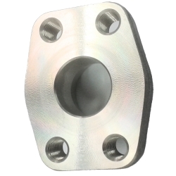
Flat Side SAE Flange
7. Types of O-ring sealing used:
It is a static face seal that seals the flange with a high durometer O-ring. Metal-to-metal interactions on the flange's outer face will produce leakage. As a result, the O-ring sealing is compressed between the flat face and the O-ring face, resulting in a reliable soft sealing. Flanges utilise an O-ring to seal a connection and keep pressurised fluid in place. The following table is the materials used for seals of flanges:
| Description | Viton 90 | NBR 70 / 90 |
|---|---|---|
| Equivalent | FKM | BUNA-N |
| Temperature Range (⁰C) | -26 ⁰C to 205 ⁰C | -34 ⁰C to 121 ⁰C |
| Non-Recommended Application |
|
|
| Recommended Application |
|
|
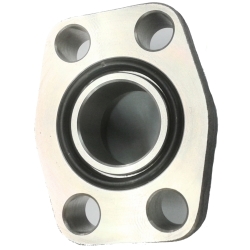
O-ring Side SAE Flange
8. How to assemble SAE Flanges:
SAE Flanges are used for high pressure hydraulic applications. In order to use and assemble SAE Flanges safely, it is important to know the correct procedures and torque range for assembly.
STEP 1
- Ensure the sealed surface is free from scratches and contamination.
- Lubricate the O-ring surface with system fluid or a compatible lubricant.
STEP 2
- Position the flange.
- Place the washer on the cap screws and bolt them through the bolt holes.
STEP 3
- Tighten the cap screws by hand.
- Torque the cap screws gradually in a diagonal sequence to the level in the torque table below.
STEP 4
- Tighten the cap screws according to the torque table below.
3000 PSI Series (Code 61) Screw Torque:
| Metric Size | Flange Size | Screw Thread | Screw Torque (NM) |
|---|---|---|---|
| 13 | 1/2" | M8 | 32 |
| 19 | 3/4" | M10 | 70 |
| 25 | 1" | M10 | 70 |
| 32 | 1 1/4" | M10 | 70 |
| 38 | 1 1/2" | M12 | 130 |
| 51 | 2" | M12 | 130 |
| 64 | 2 1/2" | M12 | 130 |
| 76 | 3" | M16 | 295 |
| 89 | 3 1/2" | M16 | 295 |
| 102 | 4" | M16 | 295 |
| 127 | 5" | M16 | 295 |
6000 PSI Series (Code 62) Screw Torque:
| Metric Size | Flange Size | Screw Thread | Screw Torque (NM) |
|---|---|---|---|
| 13 | 1/2" | M8 | 32 |
| 19 | 3/4" | M10 | 60 |
| 25 | 1" | M12 | 60 |
| 32 | 1 1/4" | M12 | 92 |
| 38 | 1 1/2" | M16 | 150 |
| 51 | 2" | M20 | 150 |
| 64 | 2 1/2" | M24 | 150 |
| 75 | 3" | M30 | 295 |
Specifications
Technical data
| Size Range | 1/4" to 5" |
|---|---|
| Design Standard | SAE J518 ISO 6162 |
| Connections | Socket Weld Butt Weld NPT BSPP |
| Material | Steel ST52.3 AISI SS316L |
| Working Pressure | Up to 210 BAR 420 BAR |
| Origin | Italy |
| AISI SS316L | Excellent corrosion resistance. Excels in environments with high moisture and chemical exposure. Lower tensile strength compared to steel. |
|---|---|
| Steel ST52.3 | Exhibiting good corrosion resistance, it may require additional protective measures in corrosive environments. Boasts high tensile strength and toughness, suitable for heavy-duty hydraulic applications |
| Description | Code 61 | Code 62 |
|---|---|---|
| Series | 3000 | 6000 |
| Size | 3/8” to 5” | 3/8” to 3” |
| Working Pressure (bar) | 34 to 345 | 414 |
| Description | Viton 90 | NBR 70 / 90 |
|---|---|---|
| Equivalent | FKM | BUNA-N |
| Temperature Range (⁰C) | -26 ⁰C to 205 ⁰C | -34 ⁰C to 121 ⁰C |
| Non-Recommended Application |
|
|
| Recommended Application |
|
|
| Metric Size | Flange Size | Screw Thread | Screw Torque (NM) |
|---|---|---|---|
| 13 | 1/2" | M8 | 32 |
| 19 | 3/4" | M10 | 70 |
| 25 | 1" | M10 | 70 |
| 32 | 1 1/4" | M10 | 70 |
| 38 | 1 1/2" | M12 | 130 |
| 51 | 2" | M12 | 130 |
| 64 | 2 1/2" | M12 | 130 |
| 76 | 3" | M16 | 295 |
| 89 | 3 1/2" | M16 | 295 |
| 102 | 4" | M16 | 295 |
| 127 | 5" | M16 | 295 |
| Metric Size | Flange Size | Screw Thread | Screw Torque (NM) |
|---|---|---|---|
| 13 | 1/2" | M8 | 32 |
| 19 | 3/4" | M10 | 60 |
| 25 | 1" | M12 | 60 |
| 32 | 1 1/4" | M12 | 92 |
| 38 | 1 1/2" | M16 | 150 |
| 51 | 2" | M20 | 150 |
| 64 | 2 1/2" | M24 | 150 |
| 75 | 3" | M30 | 295 |
Downloads
Catalogues & literature
Catalogue
Watch
Product video
Having a hard time finding the right parts?
We stock 15,000+ line items and can source specials nobody else can. Get a quotation within 2 hours.