 Get a Quote
Gate Valves
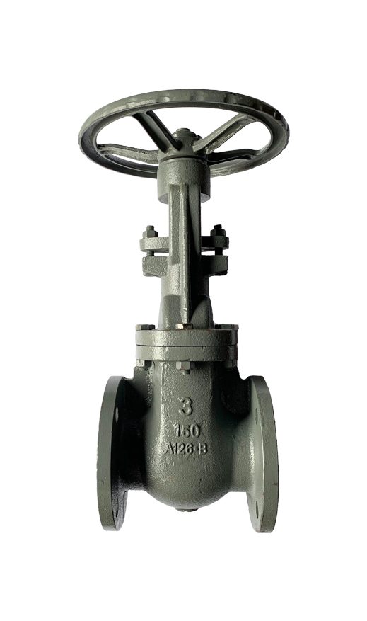
ANSI 150# Cast Iron Flange End Gate Valve
ANSI 150# Cast Iron Flange End Gate Valve. Rising/non-rising stem; minimal pressure drop when fully open; for isolation duty, operated fully open or fully closed. Body in Cast Iron GG25, rated ANSI Class 150# (PN20). Cost-effective for water and low-pressure utility lines.
- Bubble-tight shut-off (soft-seated types)
- Corrosion-resistant materials
- Ex-stock in common sizes
- Actuation options on request
Brand AF Hydro
AF HydroSpecifications
| Size Range | 2” to 6” |
|---|---|
| Connections | ANSI 150# Flange End Connection |
| Design and Manufacture Standard | ASME B16.10 / API 600 / API 602 |
| Working Pressure | 150 PSI |
| Valve Body Material | Cast Iron |
| Applicable Medium | General Oil, Gas & Water applications |
| Temperature Range | ≤ 205°C |
Specifications are indicative and vary by size and manufacturer. Request the full datasheet for exact dimensions, materials and certification.
Typical applications
- Water, seawater and utility distribution
- Compressed air and low-pressure gas
- Steam and condensate (rated types)
- Marine, building services and process lines
Ordering & procurement
Ex-stock in Singapore, dispatched within 3 working days. Material / mill certificates (EN 10204 3.1) and export documentation available. Special sizes and materials sourced on request.
Request a quoteProduct Information
Specifications
Gate valve is valve that installed on hydraulic systems to allow or cut off the fluids flow through the valve passage. The wedge can be lift up or lift down by rotate the wheel handle according to the direction of “open” and “close” which mark on handle. It is design and manufacture according to various standard such as ASME B16.10, API 600, and API 602. It will be inspected and tested according to API 598.
Material and Design
ANSI 150# Flange End Gate Valve is available in several materials such as forged steel A105, stainless steel SS316, cast iron A126B, and cast steel WCB. The materials can be select accordingly by refer to the system requirement. For ANSI 150# gate valve, the cover is design in bolted bonnet type where bolts and nuts are used to tighten the cover with the valve body.
The stem which is one component part of gate valve, is available in rising stem design and non-rising stem design. For rising stem design, it mean that the stem will rise when the handle is rotate to open position and descend when the handle is rotate to close position. This design tell us if the valve is in open position or closed position by looking at the amount of stem exposed. Alternatively for non-rising stem design, the valve is fully open when the handle is rotate to open position as far as possible and fully close when the handle is rotate to close position as far as possible. Non-rising stem design gate valve is suitable to install on tight places where there is not enough space for the stem to raise, for example, underground pipe systems.
Do check with us for the availability of gate valve design.
Connection Type
For ANSI 150# series flange end gate valve, the another connection end need to be in ANSI 150# flange connection as well. The number of bolt hole is depend on the valve size. For example, for valve size that below 4”, there are only 4 bolt hole on the flange. While for valve size that above 4”, there are 8 bolt hole on the flange. Bolts, nuts, and gasket are required whenever there are any flange to flange connection.
For more information regarding gate valves, please refer to en.wikipedia.org/wiki/Gate_valve.
Material List
| NO | PART NAME | MATERIAL |
|---|---|---|
| 1 | Body | A126 B Cast Iron |
| 2 | Wedge | A126 B Cast Iron |
| 3 | Stem | A276 SS304 |
| 4 | Bolts | A29 1035 |
| 5 | Nuts | A29 1025 |
| 6 | Gasket | SS304 + Graphite |
| 7 | Bonnet | A126 B Cast Iron |
| 8 | Packing | Flexible Graphite |
| 9 | Pin | A29 1045 |
| 10 | Packing Gland | A276 SS304 |
| 11 | Gland Flange | A126 B Cast Iron |
| 12 | Eye Bolts | A351 CF8M |
| 13 | Nuts | A29 1025 |
| 14 | Stem Nut | A276 SUS410 |
| 15 | Cover | A29 1025 |
| 16 | Handwheel | A47 32510 Malleable Iron |
| 17 | Nut | A29 1025 |
Main Technical Parameters
| Nominal Pressure | CLASS 150 |
|---|---|
| Hydraulic body test pressure | 2.06 MPa |
| Seal Test | 1.57 MPa |
| Hermetical Sealing Test | 0.6 MPa |
| Max Working Temperature | ≤ 205°C |
Technical Specifications
- Basic design and manufacture according to API 600
- Face to face dimension: ASME B16.10
- Flange End: ASME B16.5 RF
- Inspection and test: API 598
Dimensional Drawing
Frequently Asked Questions
What is the size range of ANSI 150# cast iron flange end gate valves?
For ANSI 150# cast iron flange end gate valves, the size range is from 2 inches to 6 inches.
What is ANSI 150# cast iron flange end gate valves made of?
It is made of cast iron.
What is the working pressure of ANSI 150# cast iron flange end gate valves?
The working pressure that ANSI 150# flange end gate valves can withstand is up to 150#.
What is the function of ANSI 150# cast iron flange end gate valves?
The function of ANSI 150# cast iron flange end gate valves is to block the flow of fluids in a system by using a gate or wedge type disc.
What is the type of connection for ANSI 150# cast iron flange end gate valves?
ANSI 150# Flange connection.
What is the difference between a gate valve and a ball valve?
Ball valves are more reliable and long-lasting than gate valves in terms of creating a tight seal. While gate valve has an internal disc or wedge to allow flow process and the cost is slightly lower than ball valve.
Related Product of Gate Valves
 ANSI 150# SS316 Flange End Gate Valve
 JIS 10K SS316 Flange End Gate Valve
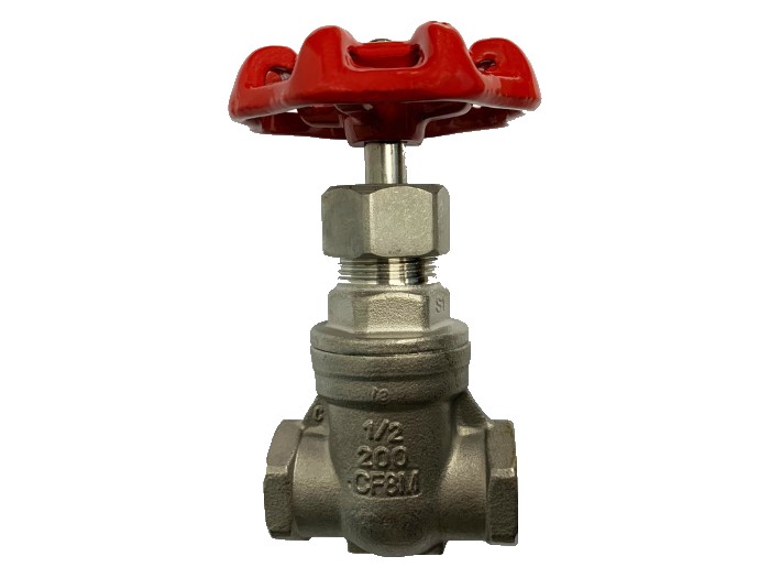 Threaded End SS316 Gate Valve 200PSI
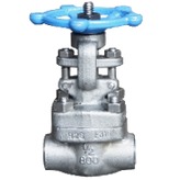 Threaded End SS316 Gate Valve 800PSI
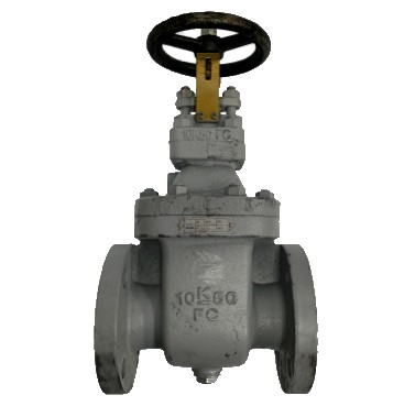 JIS 10K Cast Iron Flange End Gate Valve
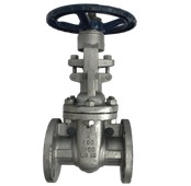 ANSI 150# Cast Steel Flange End Gate Valve
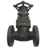 ANSI 150# Forged Steel Flange End Gate Valve
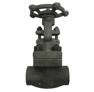 Threaded End Forged Steel Gate Valve
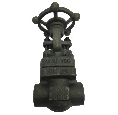 Welded End Forged Steel Gate Valve
Having a hard time finding the right parts?
We stock 15,000+ line items and can source specials nobody else can. Get a quotation within 2 hours.